
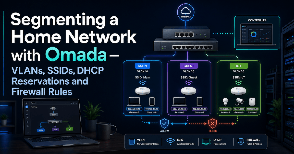
A flat home network puts your laptop, your IoT gadgets, and your guests on the same wire. Here's how I carved my house into isolated zones with TP-Link Omada — VLANs, dedicated SSIDs, DHCP reservations, and firewall rules that actually keep them apart.
I recently reorganized my home network using a TP-Link Omada setup. The goal was not to build an enterprise-grade network, but to get something cleaner, safer, and easier to reason about.
The main objectives were:
| Goal | Why |
|---|---|
| Map all devices | Know what is connected and where |
| Separate trusted devices from IoT | Reduce blast radius if an Internet of Things (IoT) device is compromised |
| Keep media devices usable | TVs and audio devices often need local discovery |
| Keep guests isolated | Guest devices should not reach internal devices |
| Use DHCP reservations | Stable IPs without configuring static IPs manually on devices |
| Avoid overengineering | Simple enough to maintain |
Sensitive values in this post are intentionally anonymized.
Starting point
The house already had an Omada Controller managing the network.
The topology was roughly:
There was one main LAN:
LAN - Main
VLAN ID: 1
Subnet: 192.168.X.0/24
Gateway: 192.168.X.1
The /24 means that the network has 254 usable addresses:
192.168.X.1   gateway
192.168.X.2   device
...
192.168.X.254 device
Key concepts
| Concept | Meaning |
|---|---|
| SSID (Service Set Identifier) | The Wi-Fi name devices connect to |
| LAN / Network | The IP network behind the SSID or wired port |
| VLAN (Virtual LAN) | A tagged network segment |
| Gateway | The router/firewall between networks and the Internet |
| DHCP (Dynamic Host Configuration Protocol) | Service that assigns IPs automatically |
| DHCP reservation | Always gives the same IP to a specific device MAC (hardware) address |
| ACL (Access Control List) / firewall rule | Controls which networks can communicate |
A useful mental model:
SSID = door into the network
VLAN = separated room
Firewall rule = locked or unlocked door between rooms
Final VLAN plan
I kept the design intentionally small.
| VLAN | Name | Subnet | Purpose |
|---|---|---|---|
1 | LAN - Main | 192.168.X.0/24 | Trusted devices and media devices |
30 | LAN - IoT | 192.168.Y.0/24 | Smart appliances and weak IoT |
40 | LAN - Guest | 192.168.Z.0/24 | Visitor devices |
I considered separate Media and Security VLANs, but decided not to create them yet. TVs, streamers and audio devices often need local discovery, so moving them too early can break casting and control apps.
SSID plan
| SSID | VLAN | Purpose |
|---|---|---|
home-main | LAN - Main | Trusted phones, laptops, media devices |
home-iot | LAN - IoT | Smart appliances and IoT |
home-guest | LAN - Guest | Visitors |
The IoT SSID was configured for compatibility:
| Setting | Value |
|---|---|
| Band | 2.4 GHz only |
| Security | WPA2-PSK / AES |
| WPA3 | Disabled |
| PMF (Protected Management Frames) | Disabled or optional |
| Fast roaming | Disabled |
| Band steering | Disabled |
| Password | Unique, long, easy to type |
For IoT, boring is good. Many smart devices behave badly with WPA3, band steering, roaming optimizations or 5 GHz-only networks.
Device classification
The important decision was not “is this device smart?”, but “how does this device need to communicate?”
| Device type | Network | Reason |
|---|---|---|
| Laptops | LAN - Main | Trusted |
| Phones | LAN - Main | Trusted controllers |
| Omada Controller | LAN - Main | Infrastructure |
| Gateway / switches / APs | LAN - Main | Infrastructure |
| TV used for casting | LAN - Main | Needs discovery |
| Audio streamer | LAN - Main | Needs discovery |
| Oven / appliances | LAN - IoT | Cloud-controlled IoT |
| Domotics hub | LAN - IoT, after testing | Depends on local needs |
| Alarm panel | LAN - Main for now | Critical; avoid breaking it |
| Guest devices | LAN - Guest | Fully untrusted |
The key rule:
Cloud-controlled device → IoT VLAN
Local-discovery device → Main for now
Critical unknown device → Main until tested
DHCP reservations
Instead of manually setting static IPs inside devices, I used DHCP reservations from Omada.
A DHCP reservation means:
When this MAC address asks for an IP, always give it this IP.
This keeps Omada as the source of truth.
Main LAN ranges
| Range | Purpose |
|---|---|
.1 | Gateway |
.2 - .19 | Infrastructure / security |
.20 - .49 | Services |
.50 - .79 | Trusted personal devices |
.80 - .99 | Media |
.100 - .254 | Dynamic DHCP pool |
Example structure:
| Device type | Example reserved range |
|---|---|
| Gateway | .1 |
| Controller | .7 |
| Laptop Ethernet | .10 - .19 |
| Laptop Wi-Fi | .50 - .59 |
| TV / audio | .80 - .89 |
IoT LAN ranges
| Range | Purpose |
|---|---|
.1 | Gateway |
.10 - .19 | IoT hubs |
.20 - .39 | Cameras |
.40 - .59 | Appliances |
.100 - .254 | Dynamic IoT DHCP |
DHCP lease time
| Network | Lease time |
|---|---|
LAN - Main | 1440 min |
LAN - IoT | 1440 min |
LAN - Guest | 120-240 min |
A lease time does not force devices to change IP immediately. It only controls how often they renew. To force a specific device to get its new reserved IP, reconnect Wi-Fi, reboot the device, or unplug/replug Ethernet.
Firewall / ACL policy
VLANs alone are not the full security boundary. The gateway can route between VLANs unless ACL/firewall rules block that traffic.
The final policy was:
Guest → Main   BLOCK
Guest → IoT    BLOCK
IoT   → Main   BLOCK
IoT   → Guest  BLOCK
Main  → IoT    ALLOW
All   → Internet ALLOW
In Omada, these are Gateway ACL rules because they control traffic between VLANs/subnets.
These rules block traffic by direction of the initiating connection. Because the gateway is stateful, Main → IoT ALLOW plus IoT → Main BLOCK still lets replies to a Main-initiated session return — IoT simply cannot start a connection to Main. You don't need an extra "established/related" allow rule for the return path.
If Omada supports multiple destinations per rule, the policy can be reduced to two rules:
| Rule | Source | Destination | Action |
|---|---|---|---|
Block Guest to Internal | LAN - Guest | LAN - Main, LAN - IoT | Deny |
Block IoT to Internal | LAN - IoT | LAN - Main, LAN - Guest | Deny |
If multiple destinations are not supported, create four explicit rules:
| Rule | Source | Destination | Action |
|---|---|---|---|
Block Guest to Main | LAN - Guest | LAN - Main | Deny |
Block Guest to IoT | LAN - Guest | LAN - IoT | Deny |
Block IoT to Main | LAN - IoT | LAN - Main | Deny |
Block IoT to Guest | LAN - IoT | LAN - Guest | Deny |
The result:
Guest network bandwidth limit
For guest Wi-Fi, I used per-client rate limiting.
| Direction | Limit per client |
|---|---|
| Download | 5 Mbps |
| Upload | 1 Mbps |
This is enough for basic browsing and roughly 720p YouTube, but prevents guests from saturating the connection.
Why media devices stayed in Main
Some devices are technically IoT but behave more like local media infrastructure.
Examples:
| Device | Why it stayed in Main |
|---|---|
| TV | Needed casting/discovery from phone |
| Audio streamer | Needed app discovery/control |
| Printer / NAS (network-attached storage), if present | Often need local access |
Protocols like mDNS, Bonjour, SSDP, UPnP, AirPlay, Chromecast and DLNA often assume devices are on the same local network.
So the safer initial decision was:
Media devices stay in Main.
Weak cloud-only devices move to IoT.
Later, a dedicated LAN - Media could be created with mDNS reflection, but that adds complexity.
What I learned
| Lesson | Explanation |
|---|---|
| VLANs separate networks, but ACLs enforce policy | Segmentation without rules is incomplete |
| DHCP reservations are better than manual static IPs | One source of truth |
| IoT should be boring | 2.4 GHz, WPA2, no fancy roaming |
| Not all smart devices belong in IoT | TVs and audio devices often need local discovery |
| Guest and IoT should be separate | Guests should not see your IoT devices |
| Start small | Main + IoT + Guest is enough for most homes |
Final architecture
LAN - Main
- Trusted devices
- Network infrastructure
- Media devices needing discovery

LAN - IoT
- Appliances
- Smart devices
- Weak/cloud-controlled devices

LAN - Guest
- Visitors
- Internet only
Security posture:
Main can manage IoT.
IoT cannot reach Main.
Guests cannot reach Main or IoT.
All networks can reach the Internet.
This gives a good balance: safer than a flat home network, but still usable.